
Page 77 - Lockwell Industrial Catalogue
P. 77
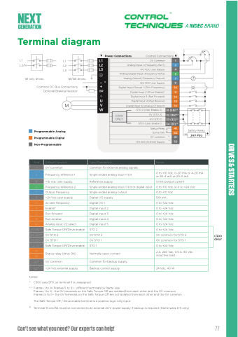
                                                                                                                                            Terminal diagram
L1
L2/N L2
1Ø only drives
Power Connections
Control Connections
                  OV Common
1
   L1 L3
                   Analog Input 1 (Frequency Ref 1)
2
                 +10 VDC User Supply
4
           Analog/Digital Input (Frequency Ref 2)
5
        1Ø/3Ø drives
    –* +
BR
Analog Output (Frequency Output)
7
  +24 VDC User Supply
9 10
    Common DC Bus Connections Optional Braking Resistor
Programmable Analog Programmable Digital Non-Programmable
  Digital Input/Output 1 (Zero Frequency)
         Digital Input 2 (Drive Enable)*
11
         Digital Input 3 (Run Forward)
12
          Digital Input 4 (Run Reverse)
13
           Digital Input 5 (Analog 1/1 Select) STO 2 (User Enable 2) 0V (STO 2)
14
          31 (35)** 32 (36)**
                   C300 ONLY
       0V (STO 1)
      STO1 (User Enable 1)
33 (32)**
 34 (31)**
             Status Relay (Drive OK)
41
  _ Safety Relay +
      Common for external analog signals
42
 24V PSU
  0V common †
  51
   +24 VDC External Supply †
52
      Pin#
Default Function
Type/Description
Notes
      1
0V Common
         2
Frequency reference 1
Notes: /
* C300 uses STO, so terminal 11 is unassigned
Notes:
* Terminal notaailvable on frame size 1. •Forframesize5tSoTO9i:nputterminals
Single ended analog input 11 bit
0 to +10 Vdc, 0-20 mA or 4-20 mA or 20-4 mA or 20-0 mA
       4
+10 Vdc user supply
Reference supply
5 mA Output current
        5
Frequency reference 2
Single ended analog input 11 bit or digital input
0 to +10 Vdc or 0 to +24 Vdc
        7
Output frequency
Single ended analog output
0 to +10 Vdc
       9
+24 Vdc user supply
Digital I/O supply
100 mA
       10
At zero frequency
Digital I/O 1
0 to +24 Vdc
       11
Enable*
Digital input 2
0 to +24 Vdc
       12
Run forward
Digital input 3
0 to +24 Vdc
        13
Run reverse
Digital input 4
0 to +24 Vdc
       14
Analog input 1/2 select
Digital input 5
0 to +24 Vdc
         31 (35)**
Safe Torque Off/Drive enable
STO 2
0 to +24 Vdc
         32 (36)**
0V STO 2
0V STO 2
0V common for STO 2
C300 ONLY
         33 (32)**
0V STO 1
0V STO 1
 Normally open contact
0V common for STO 1
        34 (31)**
Safe Torque Off/Drive enable
STO 1
0 to +24 Vdc
         41
Status relay (drive OK)
2 A, 240 Vac, 0.5 A, 30 Vdc inductive load
      42
         51 †
0V common
Common for backup supply
       52 †
+24 Vdc external supply
Backup control supply
24 Vdc, 40 W
    ** Frames 1 to 4 (Frames 5 to 9) - different terminals by frame size
are 31 and 3S5TO; 0V terminals are 32 and 36.
Frames 5 to 9 - the 0V terminals on the Safe Torque Off are not isolated from each other and the 0V common
The Safe Torque Off / Drive enable terminal is a positive logic only input
† Terminal 51 and 52 must be connected to an external 24 V power supply if backup is required (frame sizes 6-9 only)
Frames 1 to 4 - the 0V terminals on the Safe Torque Off are isolated from each other and the 0V common
Can't see what you need? Our experts can help!
DRIVE SPECIALISTS SINCE 1973 11 77
 DRIVES & STARTERS
